
Optimization 2:
Layer Recognition, Purging, and Colors
Layer Recognition, Purging, and Colors
Recognition of the Layer Structure
- Assign the PDF Layer Structure to DWG or DXF (if Available)
- Sort Elements on a Separate Layer According to Entity Color
- Sort Elements on Separate Layers According to Entity Line Weight
When creating a PDF file, a PDF layer structure can be assigned. Unfortunately, this feature is rarely used. The layer structure in PDF has a tree-like structure. In contrast, the layer structure in DWG or DXF is flat. Print2CAD offers the possibility to convert the tree-like structure from PDF to the flat layer structure of DWG or DXF.
Print2CAD offers the possibility to create a layer structure based on the colors of PDF elements. If the recognition function is activated, all elements will be sorted by color into separate layers. The layers receive the name: Color-[Number] or Color-[RGB]. Under certain circumstances this function may create too many layers so we recommend to change the colors to 10 index colors. This feature can be combined with the option “Sort Elements onto Separate Layers According To Entity Line Weight.”
Print2CAD offers the possibility to create a layer structure based on the line weight of PDF elements. If the recognition function is activated, all elements will be sorted by line weight into separate layers. The layers receive the name: Width-[Number]. This feature can be combined with the option Sort Elements onto Separate Layers According to Entity Color.
Important:Line width is only available in DWG or DXF file version 2004 and higher. Therefore if necessary, change the target version to 2004 or higher.
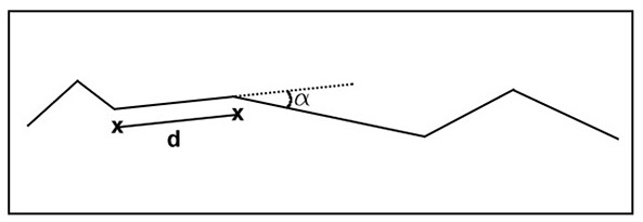
Purge Short Distance Polyline Vertices and Generate Polyline (Data Reduction)
- Some PDF files contain paths with many small distances between vertices. It produces a lot of coordinate information and it increases the drawing data amount.
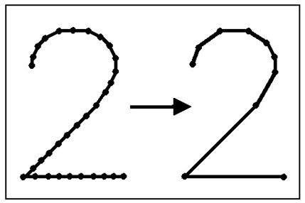
- You can reduce the number of vertexes in paths if you delete all vertexes with smaller distance to its neighbor than the given distance. Because the deleting of vertexes can phase the corners, the parameter Max. Angle Alternation helps the program to recognize the corners.
- PDF files can contain paths with many points (vertexes). Even a large amount of path data can easily be processed in PDF, because paths do not have many Settings and properties. After the conversion in DWG or DXF, every path segment becomes a full CAD line or polyline. These single CAD elements may include many additional Settings and properties.
Delete Short Lines (Data Reduction)
- Some PDF files contain paths with many small lines. This happens mostly when dotted lines have been generated in PDF files as single lines. These single lines can easily be converted to PDF as the paths do not have many Settings or properties.
- After the conversion in DWG or DXF, every line will be a full CAD line and may feature many additional Settings and properties. This data may strain the capacities of a CAD system and RAM.
- The minimum allowed line length can be set with the parameter “Smallest Line”. If a line is smaller than the parameter “Smallest Line” then the line gets deleted.
Important:
Dotted lines or hatches may be deleted completely, and therefore may not be available in the created DWG or DXF file.
Generate Circles and Arcs
.jpg)
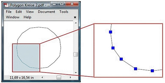
- Many PDF files contain circles and arcs that have been converted into polylines. These polylines tend to be imprecise making it difficult to detect them as a circle or arc.
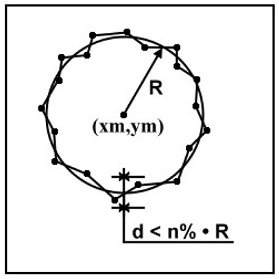
- Although the recognition of a polyline as a circle or arc appears to be easy when one looks at a PDF (a person can immediately recognize the circle or arc), the software has to work a little harder to do this.
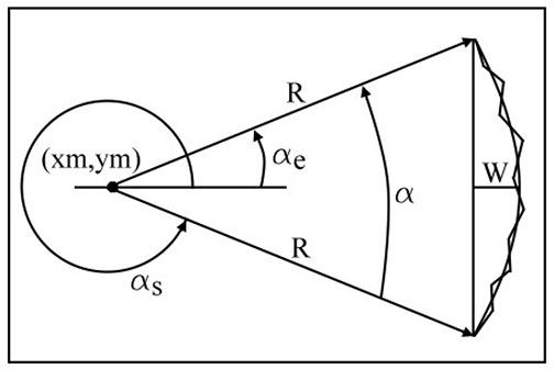
When a conversion generates arcs upside down, the radius deviation R in % was set too high.
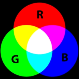
Assign RGB color space
- Print2CAD allows the user to assign RGB colors to all converted elements. An RGB color space is any additive color space based on the RGB color model. A particular RGB color space is defined by the three chromatic colors red, green, and blue additive primaries.
The color Black in a PDF is converted into the color White in CAD. The color White in a PDF is converted into the color White in CAD too.
Assign 256 Index Color
- Print2CAD allows the user to assign the 256 AutoCAD® Index Colors into the resulting DWG or DXF elements.
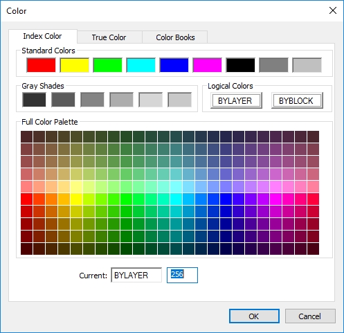
Assign first 10 Index Color
Print2CAD allows the user to assign the first 10 of 256 AutoCAD® Index Colors into the resulting DWG or DXF elements. These colors are:- Red
- Yellow
- Green
- Cyan
- Blue
- Magenta
- Black/White
- Bright Grey
- Grey
- Dark Grey
Assign Uniform Color to All Elements
- Print2CAD allows the user to assign a uniform color to all converted elements.
Assign Line Weight to Entities
- The program Print2CAD allows the user to assign a PDF line weight to all DWG or DXF elements. Contrary to DWG elements having compulsory line weights, PDF elements can have any user-defined line weight.
The PDF line weight may have any user-defined value, for example 0.27mm or 1.675 mm.
.jpg)
Line weight is only available in DWG or DXF version 2004 and higher. If necessary, change the target version to 2004 or higher.
Important:
Line weights can also be defined as a hatch in PDF files. We gave this line weight the name “Line Weight Fake”.
- Turn off the line weight view in the Adobe Reader under “View Line Weights”. If the lines do not appear with line weight 0.0, then no real line weights exist, but rather hatches displaying line weight. When converting, it can be difficult to find the appropriate line weight in DWG or DXF.
.jpg)
Another difficulty is if multiple PDF lengths exist in the same area.
For example: A PDF features the line weights 1.82, 2.56, 3.56mm.
.jpg)
- The converted DWG will only feature one line weight, which in this case would be 2.11mm, which is an ISO standard line weight.
- Our suggestion for this would be to use the scaling factor for line weights. By using this factor, the user can enlarge or reduce the line weights in the PDF.
Hatch Conversion
- When working with PDF, there is not much difference between paths and hatches. PDF hatches are defined as paths with the annotation “filled.” This increases the load speed of the PDF file. However, DWG or DXF files may open very slowly when featuring numerous hatches.
- A real hatch in a DWG or DXF file features many additional attributes and qualities. Therefore a hatch may be a heavy burden for the load speed of a CAD drawing.
- Although AutoCAD is able to handle the impressive amount of about 50,000 hatches, it slows down the program. However, many other CAD systems are not able to handle such a large amount of hatches. Print2CAD has a maximum amount of hatches defined in the configuration (default 50,000). If a PDF features more than the maximum of hatches, only the boundaries of the remaining hatches will be converted.
Delete all Hatches
- When these features are selected, the hatches are not converted. Only the boundary of the hatches are represented as polylines.
- If the PDF file was created using an HPGL interface the hatching boundaries may have loops. These loops are interpreted differently in DWG or DXF than in HPGL. They are possibly left empty. In such cases, delete all hatches and only output the hatching boundaries.
Convert Boundary of Hatch
- This function outputs all hatch boundaries as polylines.
Sort Hatches onto the Layer
- When this feature is selected the hatches are sorted onto the given layer.