
Text Conversion
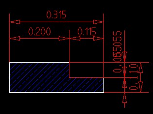
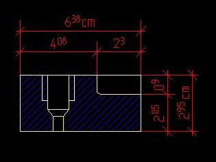
In some instances after CAD data exchange, the individual text characters in target CAD do not match those of the original, especially special characters. This is because different assignments of the ASCII numbers to the different characters cause problems with text visibility. Another reason for this problem could be the lack of UNICODE in text.
The “Text” in CAD is not only the text that is visible on a screen; it is also all other hidden texts (such as: multi-text, dimensions, attributes, attribute names, layer names, Linetype names, text style names, and block names).
In all previous CAD systems, characters use ASCII character encoding. Unfortunately, ASCII tables are limited to a maximum of 256 character symbols, which is not sufficient enough to show all possible special characters from different languages and different sciences.
Define the CADInLa Special Conversion Tables- here you will see all your conversion table requests in a list known as “rules”. It is possible to make an infinite number of new rules for the different text types.
Texts, Multi-Texts and Dimensions
Conversion of visible texts and annotationsAttribute Values
Conversion of block attribute valuesNames of Attributes, Layers, Linetypes, Text-styles
Conversion of definition names. The Layer Name can also be changed using the “Tables for Layer Conversions”. If you translate the drawing from one language to another, the option to change the layer names using this table can be very comfortable.Block Names
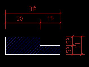
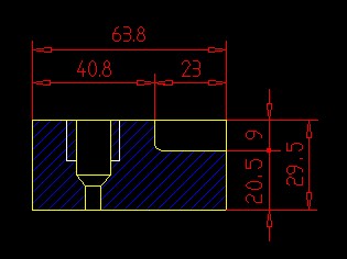
Conversion of Block Names and Element “Insert” NamesBefore Conversion:
After Conversion:
New, Previous, Next
When selecting these options, a dialog box in which you have the option of editing the highlighted line will appear.Text Old, Text New
This interface is shown on the side panel. At the top left of the interface is a field that contains the previously used special character definition or the text which is to be replaced (text Old). Top right (Text New) is the associated substitute special character or the corresponding replacement text. These two fields can be selected with the mouse or the TAB key to change them. The syntax fields (any character string etc. are explained in the next chapter)Analysis Result
If the DWG or DXF file was previously analyzed (see chapter Analysis), selecting one of the analysis buttons will make a list of characters, and textsSuggestions
By selecting the lists, you can display a standard list of the ASCII, or UNICODE character definitions, or %% sequences used in CAD.Text Context (from the analysis)
After selecting a special character from the analysis, under the heading “Text Context”, a maximum of five different text passages are displayed in which the character is used. It is often the only way to determine the meaning of a special character. For example, when translating from English “WALL” into the Spanish word “PARED”, “Word” must be selected (or it must be written under the selection “Word”). This will ensure that only full words are transformed.© Copyright 2025 Back2CAD AI Technologies LLC. All rights reserved. Kazmierczak® is a registered trademark of Kazmierczak Software GmbH. Print2CAD, CADdirect, CAD.direct, CAD Direct, CAD.bot, CAD Bot, are Trademarks of Back2CAD AI Technologies LLC. DWG is the name of Autodesk’s proprietary file format and technology used in AutoCAD® software and related products. Autodesk, the Autodesk logo, AutoCAD, DWG are registered trademarks or trademarks of Autodesk, Inc. All other brand names, product names, or trademarks belong to their respective holders. This website is independent of Autodesk, Inc., and is not authorized by, endorsed by, sponsored by, affiliated with, or otherwise approved by Autodesk, Inc. The material and software have been placed on this Internet site under the authority of the copyright owner for the sole purpose of viewing of the materials by users of this site. Users, press or journalists are not authorized to reproduce any of the materials in any form or by any means, electronic or mechanical, including data storage and retrieval systems, recording, printing or photocopying.