
Calibration of PDF and Raster Coordinates
Enhanced Calibration of Coordinates
Print2CAD’s artificial intelligence techniques allow the accurate calibration of the coordinates of the converted drawing.
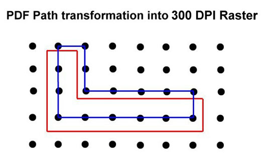
The coordinates of PDF files often have a significant accuracy error. This error is mostly created by exporting entities in a raster of 300 DPI (dots per inch).
The Print2CAD calibration method is tailored for coordinates in a raster. This calibration happens in the horizontal and vertical directions.
When calibrating the coordinates, a special feature is used that keeps the horizontal and vertical lines the same after the calibration.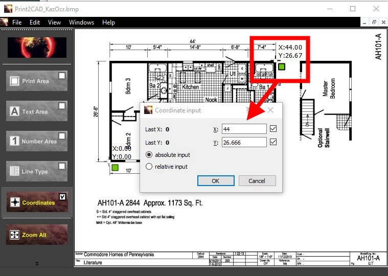
Scaling Coordinates with a Factor
Coordinates in PDF files are usually in a resolution of 300 DPI, which means that one inch (25.4 mm) equals 300 pixels and coordinate points. This resolution is adequate for paper prints, but not adequate for CAD purposes.
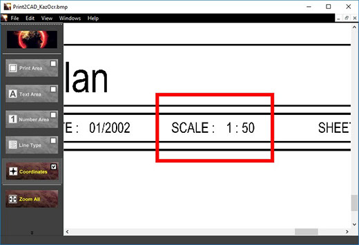
You can try to calibrate the coordinates using a common scale factor for the coordinates. In a correct PDF file, the scale of the drawing is also the scaling factor of the coordinates. For example; by scale 1:50 the scaling factor is 50. Unfortunately, the scale of a PDF drawing can only be retrieved from the header of a construction plan.
If the scaling factor doesn’t correct the coordinates well, you need the correct calibration with the help of function “Enhanced Calibration of Coordinates”.
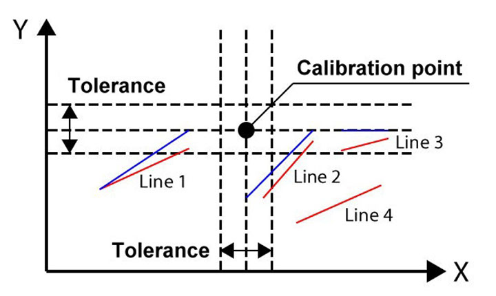
Parameter: Tolerance of a Calibration
The calibration point can be defined for arbitrary PDF lines and polylines.
Print2CAD calibrates native vectors and pixel traces from raster pictures. The pixel traces have to be vectorized before the calibration. You need to activate “Center Line Vectorization” for the lines you want to calibrate.
The calibration of coordinates is a last step of a PDF to DWG conversion. Print2CAD snaps in the defined calibration points with the given tolerance and then calibrates the snapped points with special mathematical methods.
Parameter: Minimum Line Width
You can choose the right line width for our internal editor. The line width has to be as low as possible, but the lines have to be clearly visible. Try first with 0.35 [mm]. If all lines are not visible, increase the minimum line width to the next one.Parameter: Maximum Resolution in DPI
The resolution for our internal editor has to be as low as possible, but the detail has to be very clear and readable. Try first with 300 DPI and push the button “Preview”. If the smallest text is not readable then increase the resolution 50 DPI steps.Calibration Point Definition
A manual predefinition of the calibration points is needed for well done calibration of coordinates. Print2CAD offers a special editor for the calibration points.
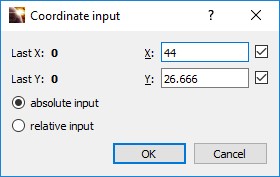
One “Calibration Point” is defined with the help of a position point and the target X,Y coordinates of this point can be absolute or relative numbers.
The position point can be the end of a line or a vertex of a polyline. You can not snap the cross point of two lines or the center of a circle.
You do not need to move the calibration point to the exact position. If the calibration point is not exactly on the vertex or on the end of a line, Print2CAD will snap to this point during the conversion using the given tolerance.
Target X, Y Coordinates of Calibration Points
The target X,Y coordinate of calibration points can be an absolute or a relative number.
Absolute X,Y Coordinate is a Cartesian Coordinate with a common absolute zero.
Relative X,Y Coordinate is a Cartesian Coordinate with a absolute zero as the last inserted point. The Relative Coordinate can only be used for input. After saving the calibration points the program recalculates the relative calibration points into absolute calibration points.
Tips:
- Define at least 2 calibration points with different X and Y coordinates
- You need about 10 calibration points for accurate calibration of coordinates
- A thorough selection of the calibration points vastly improves the quality of the calibration of coordinates
Editing of Calibration points
Calibration Points Editor allows the program to move, change, and delete the calibration points.
Calibration Points Editor allows the program to zoom any part of a drawing.